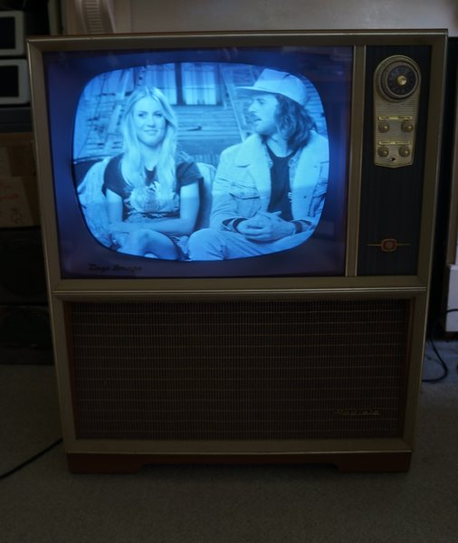
First generation 110 degree sets haven't
always appealed to me, so when I was offered an AWA 221-C from 1959, the
enthusiasm to go and get it wasn't particularly great, given that I have
run out of room for more sets.
The set to be described was from a deceased
estate at Kurrajong Heights, on the northern side of the Blue Mountains.
However, once I arrived at the house and
saw it, I started to take a liking to it. The cabinet styling was old enough
to almost pass for a 90 degree set, and it was in very good cosmetic condition.
Once home with it, and the back off, it was definitely a set worth keeping.
Several things caught my attention. It
is one of the few Australian 110 degree sets with a 5AS4 rectifier. It
is also one of the few with a two stage video amplifier, and grid drive
to the picture tube. I had been aware of this series of AWA models that
used this design, but this was the first time seeing such a set in person.
And, the audio system looked better than average, with a large 12" speaker
plus high frequency tweeter.
To add to the story of its past, the remains
of several licences were stuck to the back. The set was purchased 6/4/59.
and the "Authorised Repairer" was Woodhill & Co. Pty. Ltd, phone Richmond
8.
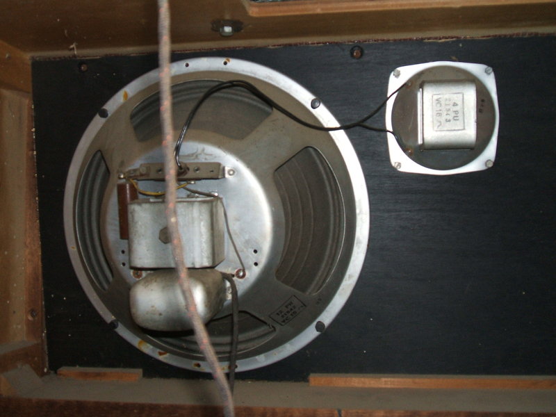
This speaker arrangement puts most sets to shame.
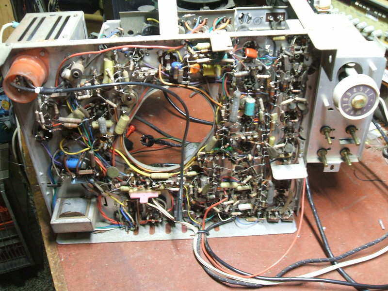
The first AWA sets using 70 and 90 deflection
used a conventional horizontal dish chassis. A sliding panel under the
cabinet allowed access to most components. When AWA started making 110
degree models, the chassis was now vertical, behind the picture tube, with
the neck and yoke protruding through the middle of the chassis. The 221-C
was of this type. Unfortunately, service access is poor, and it's not possible
to work on the component side of the chassis whilst it's in the set. The
chassis can be removed with the CRT attached, or alternatively the chassis
removed on its own and set up on the bench with a test picture tube.
A later improvement was to allow the chassis
to swing out to a limited degree, but it wasn't until the 50 series that
we had proper access with the chassis swinging down giving full access.
My acquaintance who arranged for me to
have this set implied that it had been used until recently, and mentioned
the CRT had been replaced. I was curious just to see if it did anything
when powered up. The plug had been cut off, so a temporary connection was
made. The valves lit up, but nothing else. No sign of audio or line output
activity. I found the 500mA B+ fuse open circuit, although not blown as
such. It seemed to be corrosion of the fuse wire at one of the end caps.
Replacing this at least gave a weak crackle when the volume control was
rotated, but nothing more. Time to extract the chassis.
First Inspection.
I was pleased to see that most of the
paper condensers had been replaced with polyester types, and a few of the
micas with polystyrene types. Also, a lot of the high value resistors had
been replaced. Most Australian manufacturers used IRC resistors, which
unfortunately are very unreliable, drifting high over the years. In the
past, one would have to replace all resistors over 100K, but as time has
gone on, the lower values are now also suspect, as will be evident later
on. I noticed that whoever had been serving this set had a liking for Philips
Miniwatt valves. The CRT was a Miniwatt, as were quite a few valves. The
6DQ6A was an unusual type made by Philips, in that physically it looks
like a 6CM5. I have often wondered if this Philips valve is just a rebadged
6CM5 (it appears not).. As any Australian vintage TV enthusiast knows,
the 6CM5 was the standard line output valve from the inception of
TV in 1956 right until the last valve sets in 1974, and it was used in
every line output stage of Philips design over that period, but more on
this later.
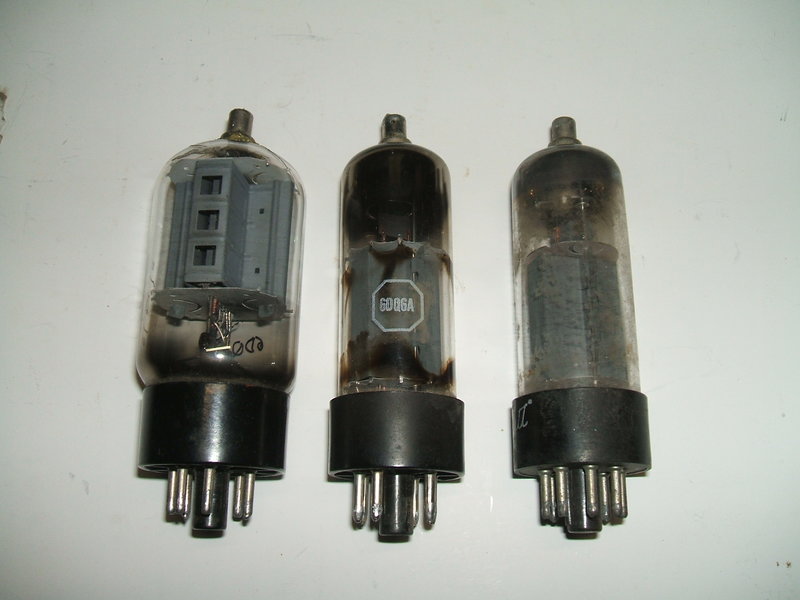
A real 6DQ6, the Philips Miniwatt version, and the 6CM5 I used for
testing.
It seemed our technician loved Philips
valves so much that when the 6U8 in the sync and AGC circuit needed replacing,
a 6BL8 was installed instead - a type never seen in AWA sets. The 6AU4
damper diode was a newish looking replacement, made in West Germany, but
no brand was visible.
The plastic covering for the back of the
deflection yoke was of a type commonly used for AWA yokes which crystalises
and crumbles apart. This one was no exception. Disturbingly, I recognised
the rubber insulation between the horizontal and vertical windings as a
type which causes problems with the copper wire.
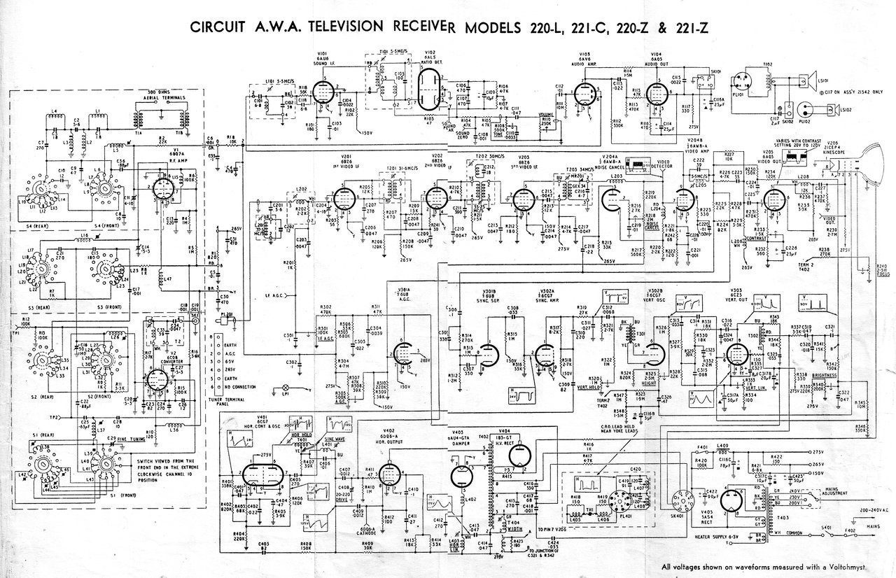
A brief description of the design will now be given:
Front End.
A ten channel incremental tuner provides
a video IF of 36Mc/s, and a sound IF of 30.5Mc/s. RF amplification is by
a 6BQ7 in cascode configuration. The frequency converter is a 6CQ8 triode
tetrode.
There are three stages of video IF amplification,
each using a 6BZ6 pentode. A solid state diode, GEX34, demodulates the
video signal.
One stage of sound IF amplification is
performed by a 6AU6 pentode operating at 5.5Mc/s. This feeds a 6AL5 ratio
detector, which demodulates the FM audio signal. No limiter is required
as the ratio detector is self limiting. However, there is a grid leak circuit
with the 6AU6 that will cause limiting once the input noise exceeds the
cathode bias voltage.
Audio Amplifier.
This consists of a 6AV6 voltage amplifier
which feeds a 6AQ5 beam tetrode output valve. Negative feedback is provided
by R114. The 6AQ5 is not operated at full ratings. Note the cathode bias
resistor is 470R instead of the usual 250R. Also, the plate load is 7K
rather than 5K. A twin speaker system is used, with a simple crossover
network to feed the tweeter. The tone control is a treble cut type in the
6AV6 grid circuit.
Video Amplifier.
Unusually, this is a two stage design,
with a 6AW8 for the first amplifier, and a 6AQ5 for the output. Conventional
design has been to feed a single high gain pentode direct from the video
detector. The picture tube is then cathode modulated by the video amplifier
plate.
However, in Australia, AWA used a two
stage amplifier in some of their early 110 degree sets. Due to two stages,
the phase reversal means the picture tube is now grid modulated, to maintain
correct picture polarity. As the intercarrier system is used, the sound
IF is taken from the plate circuit of the 6AW8 pentode. The 6AW8 also feeds
the sync separator. Since the contrast control is in the 6AQ5 part of the
circuit, it means the sync separator is fed with a constant level video
signal regardless of the contrast setting. The contrast control is of the
cathode rheostat type, providing a variable degree of negative feedback.
As the 6AW8 is a high gain valve, capable of driving a picture tube directly,
it would overload the 6AQ5, if it was not for the fact the 6AW8's plate
load is split.
The video amplifier is AC coupled, as
is the picture tube, which was originally a 21" 110 degree type, 21CEP4.
The Philips Miniwatt equivalent it had been replaced with is an AW 53-88.
Noise Cancelling.
The triode of the 6AW8 functions as a
clipper to remove noise pulses from the video signal feeding the sync separator.
A sample of video from the detector is fed into the cathode. As the stage
is operating in grounded grid mode, the amplified video signal appears
at the plate in the same phase. This is opposite to the phase of video
signal coming from the 6AW8 pentode plate, since it operates in grounded
cathode mode. Since the two signals are connected via the 0.22uF C218,
it can be seen that depending on how much the 6AW8 amplifies, the feed
to the sync separator can be cancelled out. By means of adjusting the triode
grid voltage, the video signal is cancelled out just above peak white.
Any stronger noise pulses will not be conveyed to the sync separator. The
negative grid voltage used to set the 6AW8 triode operating conditions
comes from the grid of the line output valve.
Sync Separator.
This is a conventional circuit using the
triode of a 6U8 as a sync clipper, by means of low plate voltage, and the
grid being driven positive on the sync tips. Further amplification and
clipping occurs with the following 6CG7 triode. From its plate, the deflection
oscillators are fed with just the sync pulses.
Vertical Deflection.
The oscillator is of the blocking type,
based around a 6CG7 triode. The roughly sawtooth output from the plate
feeds the output stage using a 6CZ5. An extensive feedback circuit corrects
for the distortion caused by using a pentode. Linearity is adjusted by
a cathode rheostat in the 6CZ5 circuit, which sets the optimum bias. The
6CZ5 plate load is an autotransformer which matches the low impedance deflection
coils. Vertical blanking pulses are also produced here and fed into the
picture tube cathode.
Horizontal Deflection.
Throughout their roughly 18 years of making
valve televisions, this part of AWA design did not change a great deal.
They started off with the RCA Synchroguide line oscillator and used that
until they switched to a multivibrator with AFC circuit. In the 221-C,
the Synchroguide circuit is still being used. One 6CG7 triode performs
as a blocking oscillator, and the other triode functions as an AFC circuit.
The output stage is typical, using a 6DQ6 and an autotransformer. Damping
is performed by a 6AU4, connected in the standard way so that a B+ boost
voltage is developed, allowing the 6DQ6 to work with a higher plate voltage.
Width is adjusted by shunting part of the transformer with an adjustable
choke. A secondary winding on this choke provides blanking pulses for the
picture tube. Deflection coils are connected directly to tappings on the
transformer. EHT is generated in the usual way and uses a 1B3 rectifier.
AGC.
Two systems of AGC were used by AWA during
this era. One was a simple ACG in which the detected video signal provides
the negative going AGC voltage. In some sets this was elaborated on by
including a peak level detector so the AGC voltage was representative of
the sync pulse level, and not the luminance signal. The AGC voltage is
limited to the peak level from the video detector so may not provide enought
control voltage in strong signal areas. In other sets, the negative voltage
appearing at the grid of the sync separator was used, described as "augmented
AGC" in AWA literature. This provides a slightly higher control voltage
since the sync separator is fed from the video amplifier. The other system
used is the superior gated AGC, and this is what the 221-C uses.
With this, a much higher AGC voltage is
available, and the signal strength is sampled only during the line sync
period. Therefore, the AGC is immune to fluctuations caused by scene content
in the televised picture, and it has greater control, allowing for greater
changes in signal strength. It also has better noise immunity since the
signal is only periodically sampled. Interference occuring outside the
sampling period has no effect.
In the 221-C, a 6U8 pentode rectifies
a portion of the AC voltage appearing on the line output transformer. It
is a standard shunt rectifier circuit. The negative voltage so produced
feeds the AGC circuits. The 6U8 operates as an adjustable diode. It can
be seen the more the 'diode' conducts, the greater the negative voltage.
The 'diode' conduction is controlled by the video signal fed into the grid.
The stronger the sync pulse, the more positive is the 6U8 grid, the more
effective is the rectification, and the more the AGC comes into control.
Now for the gated part: Since the AC source
for the 6U8 plate comes from the line output transformer, clearly we can
see that it is in step with the horizontal sync. That means, the 6U8 is
conducting only during this period. The result is the AGC is responsive
only to the signal during the horizontal sync. This is important, because
it is one part of the video signal that does not change with picture content.
Thus, gated AGC provides a true representation of signal strength. Simple
AGC systems are to a lesser or greater degree affected by picture content
since they continuously sample the signal.
The tuner is fed with a a greater level
of AGC than the IF strip since the RF amplifier has a greater control over
input signal. Also, as the 6BZ6 valves are sharp cut off types, the control
voltage cannot be very large without causing distortion.
Power Supply.
As is conventional with Australian design,
a transformer isolated power supply is used. Valve heaters are 6.3V and
parallel fed. The high tension comes from a secondary winding feeding a
5AS4 rectifier. This was the standard 5V television rectifier used in Australia;
it being an improved type over the 5U4. Unusually, however, by the time
110 degree sets came to Australia, most manufacturers had switched to silicon
diode rectifiers, such as 1N1763 or OA210, usually using them in a voltage
doubling circuit. Aside from being more efficient than a valve rectifier,
by using silicon diodes in a voltage doubling circuit, the transformer
only needed a secondary winding of around 115V, instead of around 560V
with a centre-tap. AWA did use solid state diodes with some early 110 degree
sets, but by the early 1960's the 5AS4 was out of fashion.
Note how control panel with tuner attaches to side of chassis for
serivicing.
No EHT.
Surprisingly, there was no EHT. Only a
very weak spark could be drawn from the 1B3 top cap. I had replaced the
boost condensers (the usual reason for no line output in an unrestored
valve set), and there was drive to the 6DQ6. Something had to be loading
it down. Two likely possibilities were the yoke or an EHT short.
Faulty Deflection Yoke.
The yoke looked suspect in that I had
seen green corrosion around part of the line coils. This yoke was a type
I have seen before in which the rubber reacts with the copper wire, causing
it to corrode and create shorted turns. I decided to run the line output
stage without the yoke to see if there was any increase in EHT. To do this
requires bridging the B+ link connections at the yoke socket. This is a
protective feature, since running a set with no yoke can damage the picture
tube due to the undeflected spot, to say nothing of the line and field
stages operating into no load. However, for a couple of seconds in a valve
set it isn't going to do any damage. The upshot was still no EHT, but a
decent spark could be taken from the 1B3 top cap if it was removed from
the 1B3. Plugging the yoke back in killed the spark - a defective
yoke! Luckily, in my collection of 110 degree yokes, I had an AWA type
for this chassis. Plugging this in allowed the high voltage at the 1B3
top cap to be produced - confirming the yoke was at fault.
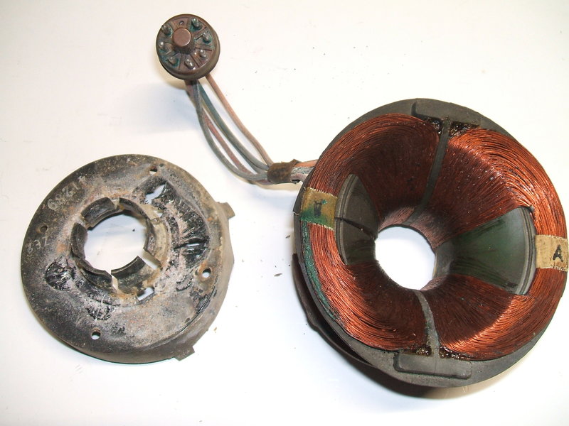
Note the green corrosion at the edge of the winding on the left
side.
Faulty 1B3.
I had observed a purple discharge inside
the 1B3 once the top cap was re-connected, and the spark at the top cap
was weak again. Evidently, the 1B3 was gassy and acting a lot like a short
circuit. Replacing it brought forth light on the screen at last! Connecting
a digital box provided a picture.
Just to confirm things, the original yoke
was tried again, and there was no EHT. A measurement of both line coils
showed a marked discrepancy in inductance and Q between them.
Intermittent line deflection.
After a couple of minutes there seemed
to be a problem with the line deflection in that it would drop out intermittently,
sometimes over a period of a few lines. It was like a bad connection somewhere.
Nothing responded to physical touching of the likely parts. Was it the
line oscillator, or line output? A test of the drive waveform showed that
to be stable. Nevertheless, I did try replacing the 6DQ6 grid coupler which
was still a mica type. It's just the kind of fault a mica condenser could
cause. Alas, a polyester type in its place didn't fix it.
The fault was predictable in that it would
always begin happening once the set was warmed up. It was temperature sensitive.
Seeing all the resistors and condensers had been replaced, the most likely
thermally sensitive component is of course the valve.
Faulty 6DQ6.
I didn't have a 6DQ6 to hand, but I did
have a 6CM5 within reach. Anyway, it would serve as a go / no-go test before
delving into my collection to find a 6DQ6. And that was it! Rock steady
line output for as many hours as I cared to run it. In fact, the 6CM5 seemed
to work very well in this position and I decided to leave it. Although
the two valves have different characteristics, operating conditions seemed
satisfactory.
It is interesting to speculate what the
fault was with the Miniwatt 6DQ6A that had been in the set, since it was
not responsive to tapping on the valve envelope, but was only heat responsive.
Weak audio.
Volume seemed weak for a set using a two
stage audio amplifier. AWA had used a single 6BV7 pentode in some of their
cheaper sets for the audio, and the gain is high enough to give passable
results fed directly from the ratio detector. These sets (such as the 212-C)
give just sufficient volume, and not much more. With the 6AV6-6AQ5 line
up in other sets, the gain should be a lot higher. One interesting thing
I noticed when connecting up the test speaker transformer, was that in
the past someone had twisted a piece of wire around the link connections
on the speaker socket. This is a protective feature, since the speaker
transformer is mounted on the speaker and not the chassis. If the speaker
is unplugged therefore, it means the output valve is running with no plate
load and the screen grid will be severely overloaded. To prevent this,
a link in the speaker plug disconnects the earth return of the output valve
when the plug is removed. Arguably, this would cause the heater to cathode
insulation rating to be exceeded, and in my opinion is not a good way to
do it. Instead, the link should have been from B+ to the screen of the
output valve.
It was noted there was only about 5V across
the 470R cathode resistor - obviously the 6AQ5 was not drawing normal current.
Not surprisingly, the grid coupler for the 6AQ5 was one of the few paper
condensers that had not been replaced by the previous serviceman.
It's a perfect example of what happens
when paper condensers are left in a set. Another 6AQ5 brought up the cathode
bias to around 13V, and the volume. This is the first 6AQ5 I can recall
replacing in my servicing career.
Vertical linearity.
Vertical output stages using pentodes
are always harder to adjust for good linearity, compared to those using
triodes, and this set was no different. While pentodes are more efficient,
they introduce distortion because of high plate resistance, and it will
be noted that vertical output stages using them always have a complicated
feedback network to correct this. Sometimes two linearity controls are
provided, one for top linearity, and another for over-all linearity. Even
so, linearity is difficult to get as good as a triode - some sets doing
better than others in regards to this.
I had noted during component replacement
that the resistor in series with the earthy end of the height control had
been replaced with 1M, when the service manual stated 820K. It was not
uncommon for a serviceman to use the next closest value when the correct
value was not to hand. Also, a not uncommon modification had been done.
The RC network in the 6CZ5 plate circuit had been removed and replaced
with a VDR. With the development of VDR's for television use in the 1960's,
many sets dispensed with the RC network, eliminating at least two components,
one being a high voltage condenser. Its purpose is to limit the high voltage
peak during vertical retrace.
It was not possible to get acceptable
bottom linearity in this 221-C as things were. This is often due to a bias
problem, and indeed, as with many sets, the linearity control is a cathode
rheostat in the output valve circuit to adjust the bias. A possibility
was the cathode bypass electro was low in value, and indeed shunting another
across it did improve linearity. However, I discovered that 50uF
on its own, as specified, was insufficient. Obviously, the circuit has
been designed with 50uF and allowed for a certain amount of AC across the
condenser (5Vp-p). Another clue is, can acceptable linearity be obtained
at reduced height? In this case it could be - something that points to
the output valve being weak. And, so it proved to be. Another 6CZ5 fixed
the problem. Incidentally, the 6CZ5 was replaced by the higher rated equivalent,
6EM5, in later sets. In fact, many such valves are labelled as 6CZ5/6EM5.
Again, like the weak audio 6AQ5, the grid coupler had been left as a paper
type, so this should perhaps not be surprising.
Tuner.
The 6CQ8 converter valve had obviously
been replaced at some stage since it was the later 6EA8, which is an improved
equivalent of the 6U8. The 6U8 and 6CQ8 are also closely related with some
types labelled 6CQ8/6U8. The tuner is an incremental type, originally of
RCA design, and is very similar to those used in the 70 and 90 degree sets.
As the 221-C was made in 1959, it has only a 10 channel tuner. Unfortunately,
there was not enough local oscillator adjustment to tune down the old channel
1 to the post-1961 channel 0. While of course the tuner could be modified
to do so, it would require extensive realignment, since with an incremental
tuner all the tuning coils are in series. Modifying one coil therefore
affects all the other channels. However, many modulators operate on channel
3, which did not have its frequency changed in 1961.
The tuner did not need any work except
to clean the contacts. The high value resistors had already been replaced.
Sync Problem.
Throughout all this work, the horizontal
sync had been very poor. It showed the classic symptom of video in the
sync; i.e., not all the luminance signal had been clipped off the sync
pulses. First point of call for sync faults like this is to see that the
video signal itself is not distorted.
This can happen if the AGC is not optimum
and the IF amplifier is overloaded, causing crushing of the sync pulses.
Alternatively, if there is any modulation on the AGC line, it will also
upset the sync pulses. The AGC should be pure DC. Heater to cathode leakage
in any of the front end valves can also cause modulation of the video signal.
The video signal from the detector was
indeed distorted with the black level being modulated by something. Adjustment
of the AGC as described in the manual fixed that. Now, there was the correct
2.5Vp-p signal from the detector. Unfortunately, the sync problem was still
there, although slightly improved.
The signal source was a Bush digital box
which has a UHF output. This is fed into a Tandy UHF converter to provide
a channel 3 output on VHF. While this set up works well with my workshop
TV's, the UHF converter can sometimes introduce modulation hum.
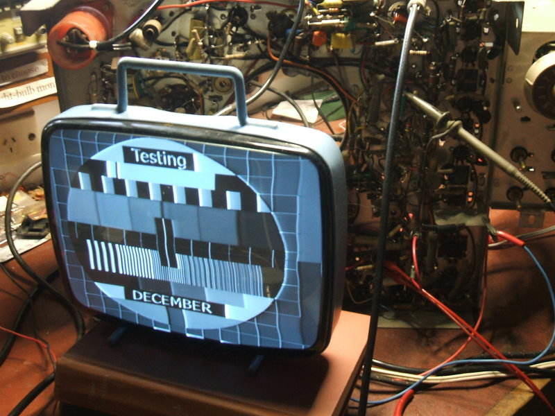
To eliminate this, I turned to my DVX
box with a Philips PM5544 test pattern generator, as
described here. The video output was fed directly into the 221-C at
its video test point. A 47uF bipolar electrolytic was connected in series
so as not to upset the DC conditions of the video circuitry. Ironically,
I was pleased to see the fault much more clearly evident, as shown below:
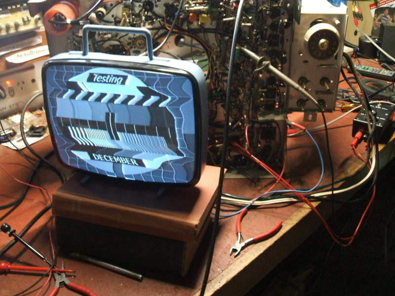
Test pattern fed directly into the first video amplifier. Line sync
is very poor.
The test pattern is designed to show up
any weaknesses in the sync circuitry, and it did so very well. One important
thing to note is that the output of the DVX box is 1Vp-p. This means that
the output from the 6AW8 1st video amplifier is less than when used with
the tuner and front end, and therefore the sync separator has less drive
to it, resulting in less effective sync clipping. However, if the circuit
is properly designed, it should still work with a reduced input. The challenge
here was to get the sync separator working with the 1Vp-p signal, and it
should be even better once operating with the normal 2.5Vp-p.
The sync separator valve being a 6BL8
had been in the back of my mind, but putting a 6U8 in didn't make much
difference. No, there must be a fault in the chassis. The 6AW8 was tried
just in case it had some peculiar fault, but as I expected it didn't.
Probing around the grid of the 6BL8 triode
did improve things. The CRO loading affected operation. It seemed like
it wanted lower grid resistance. I had already replaced all the resistors
in the grid circuit. I even tried bridging the mica condensers but that
did nothing. While idly touching a 2.2M resistor to various circuit points
it seemed that connecting it across R315 made a huge improvement. This
was illogical as there was already a new 1M resistor there. As it turned
out, when I had installed the new 1M, one of the leads had not tinned at
all.
Once this was cleaned up and resoldered
it looked like we were making progress. It was better but still a long
way off being acceptable. More probing of the sync circuit took place,
but I wondered about the sync amplifier; one half of a 6CG7. This could
also have an effect, if it was meant to provide further sync clipping.
And here was an unexpected fault. R313 was a 2.7K resistor. I had overlooked
it because of its low value, but much to my surprise, it had risen to about
6K. This goes to show that no IRC resistor is above suspicion! Resistor
values in sync circuits are often critical since they determine the level
at which the video signal is clipped, and so it proved to be here. Replacing
R318 improved things even further. In fact, with the higher level off air
signal, the set was giving quite good pictures. A non technical viewer
would probably be satisfied, but careful observation revealed there was
still some video in the sync on some scenes. So, back to the Philips test
pattern for further investigation.
Playing around with resistors did fix
the problem. Reducing the 6CG7 grid resistor R316 to around 10K did the
trick. I could have left it that way and no one would be the wiser. Modifications
like this are a sign of butchery and are used to cover up another fault.
I knew very well that AWA would not release a set with poor sync, and this
sync separator had been used in other models which I knew worked perfectly
well.
However, the lowered resistor was giving
a useful clue. It appeared that the drive to the 6CG7; i.e., the output
from the 6BL8 was not high enough to cause proper clipping. Why would it
be lower than normal? Let's look at that ring-in 6BL8 again.
6BL8 is not 6U8.
Proper sync restored with 6U8 separator valve.
While the 6U8 and 6BL8 are both triode
pentodes, with the same pin connections, and used in the same applications,
they are not the same valve. Looking at the triode, the data shows the
6U8 amplification factor to be 40, and 20 for the 6BL8.
With a 6U8 now installed, the test pattern
was very good, and even better with the VHF signal. Of course, a 6BL8 is
commonly used in sync circuits, but the other components have to suit!
If only a 6BL8 was available, then R316 could be changed to 10K.
As for the pentode section of the 6U8,
used for the gated AGC circuit, no difference was noted when the 6BL8 was
used here. There were equivalents to the 6U8, which are the 6CQ8, which
contains a tetrode instead of a pentode, and the later 6EA8. Interestingly,
the 6BL8 that had been fitted developed a fault in its triode whilst this
testing was taking place. It is interesting to consider if another pin
compatible Philips type had been used as a replacement - the 6JW8. The
amplification factor of its triode is 70.
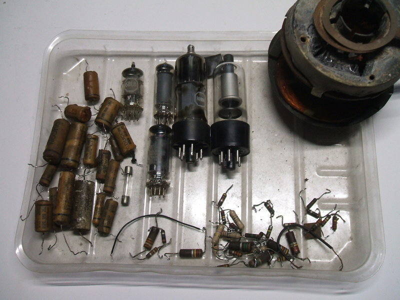
Final collection of replaced parts.
Horizontal Linearity and the 6DQ6.
At last all the chassis work was done
and preparations were made to re-install the chassis in the cabinet. I
had noticed the CRT had accumulated dirt on its viewing surface, so it
and the safety glass were cleaned. I noted a small scratch in the middle
of the CRT. Evidently, it had not been placed on the proper soft surface
prior to installation. In theory, implosion is more likely with the scratch
creating a weak point, but I've never seen it actually happen. I doubt
it will, if it hasn't happened by now.
The knobs were very difficult to remove
during the initial chassis removal, so I applied some silicone grease to
all the control shafts when replacing them. They slid on much easier, and
are less likely to break when removed again.
Given that this set looked like one that
had been used all day every day, I had wondered about the condition of
the CRT. So, it was pleasing to see it was in excellent condition. There
was no date of replacement that I could see, but the implosion warning
label looked like it was dated from 1966, so the CRT wouldn't be any older
than that.
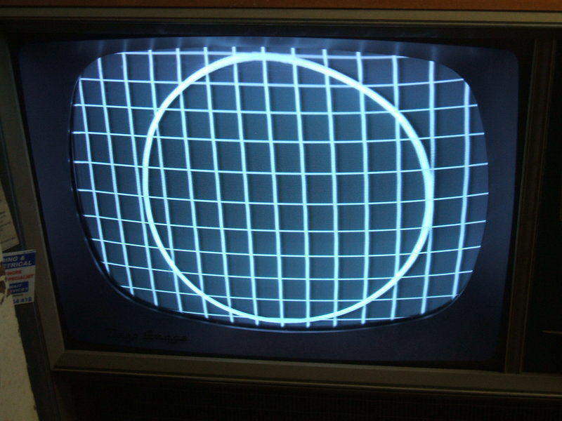
Best linearity obtained while remaining within correct 6DQ6 cathode
current.
Quite some time was spent with picture
geometry adjustment. The height and vertical linearity took a while to
get right - again confirming my dislike for pentode vertical output stages.
Unless things are just so, an obvious area of cramping occurs about an
inch below the top of the screen. It tends to stand out because the cramping
of the lines makes the picture seem brighter at this point. Anyway, with
careful manipulation, I did get good adjustment. I doubt very much that
in the field with only an off air signal, few servicemen would get as good
as I did here. They wouldn't want to spend the time on it.
The remaining adjustment was horizontal
linearity, and here things weren't so good. With the larger 21" CRT now
in use, any imperfections tend to be more obvious than with the 11" test
CRT. There was obvious cramping on the left hand side. I could get some
improvement by adjusting the linearity control, L403, but still not enough
width on the left side. Knowing the use of a 6CM5 wasn't correct, I tried
a proper 6DQ6, and that did improve things somewhat. There was more width
on the left side. But, the Philips 6DQ6 was different; the same as a "normal"
6DQ6. Thus confirming, despite appearances, it is not just a rebadged 6CM5.
It was possible to get good linearity,
but at the expense of increased 6DQ6 cathode current. With most AWA sets,
the linearity is meant to be set for minimum cathode current. This is measured
by the voltage across the cathode resistor, which is brought out to a test
point.
In this case, voltage across the 100 ohm
resistor was about 10V (i.e. 100mA), when adjusted for minimum. The instructions
state that while perfect linearity may require further adjustment, the
voltage must not be increased by more than one volt above the minimum (i.e.
11V).
However, I found best linearity to be
with a voltage of around 13V. Obviously, this was exceeding the ratings
of the line output circuit, and would shorten the life of the 6DQ6, 6AU4,
and probably the 5AS4, as well as causing the line output transformer to
run hotter.
Evidently there was some mismatch with
the replacement yoke. I didn't have another to try, so simply set for the
best I could within the rated current. I also knew full well, that horizontal
linearity defects do not show up obviously with off air programs, unlike
with vertical linearity.
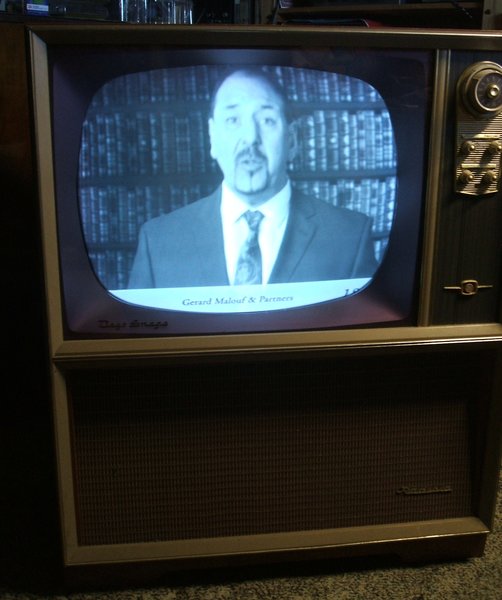
Typical picture does not show up imperfect line linearity.
This reminds me of a similar 'fault' with
a 34 series AWA chassis (model D65), where good linearity could only be
obtained by exceeding the recommended cathode current. In this situation
replacing the yoke allowed better linearity within ratings.
Given the more common 6CM5 in Australia,
it is certain that this valve has been used by some servicemen as a 6DQ6
substitute. Indeed, it had been done in my Healing 312. However, it is
well to remember that the two valves are not the same, as the data clearly
shows. It is interesting to note that AWA gave in by the mid 60's, and
started using the more efficient Philips designed 6CM5 in all their sets.
Had a suitable spare yoke not been available,
the 221-C could have been adapted to to use the later AWA yoke, as used
in the 50 series for example. The line output transformer would probably
have to be swapped over, but the modifications would otherwise be minimal.
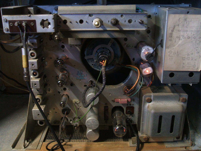
Back of chassis, finally in the cabinet.