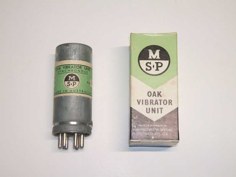
Later style label and box design.
The most popular vibrator in Australia was the MSP/Oak/AWA unit. It was exclusively used by numerous manufacturers including Ferris, Philips, Ferguson, Aegis, and of course, AWA. In fact, it was used by most manufacturers except for Astor, Air Chief, and other Electronics Industries brands, who used their Ferrocart branded vibrator. The other common Australian vibrator type was Van Ruyten, but these are high power 50 c/s units used for 240V AC inverters, and appear to have been made by Electronic Industries. Aside from these, foreign brands are sometimes seen, particularly in imported items.
Later style label and box design.
Oak Vibrators in Australia.
AWA was manufacturing vibrators in Australia,
under licence to Oak in the U.S. Initially, the vibrators were branded
AWA, but later branded MSP. "Manufacturers Special Products" was the component
manufacturing division of AWA which came into being after WW2. It was a
way to sell AWA components to competing manufacturers, as MSP was not a
brand name associated with consumer products. It can be imagined, for example,
that an AWA vibrator inside a Philips radio would look awkward from a commercial
point of view. The AWA manufactured version was based on the 1934
design, and unlike in the U.S., did not change until the cessation of vibrator
manufacturing around 1973. Oak types in the U.S. had several can styles,
many of which were crimped closed. Fortunately, AWA kept the can design
to the original type, with the mechanism secured inside by a spring clip
around the base. This makes subsequent servicing, if ever required, very
simple.
AWA's first car radio (model 74) in 1934
used an RCA vibrator, which was the same type used in the RCA M34 car radio.
The next AWA car radio model, the 153 from 1935, used a motor-generator.
A return to vibrator power supplies was coincident with the 401 in 1937.
However, it is not until the model 404
of 1938 that the service manual acknowledges that the Oak vibrator was
available as a replacement. The original vibrator for the 404 was an Electronic
type (Electronic
Laboratories). This is a shunt drive type and the manual describes
rewiring the vibrator socket to take the Oak replacement. From this, it
seems that the Oak vibrator was standard in Australia by 1939.
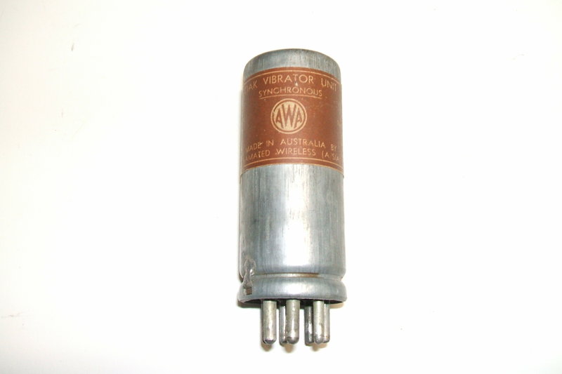
Prior to MSP coming into existance, original production was labelled
AWA.
Apart from types V5105 and V5124, most Australian type numbers are not used by Oak in the U.S. and vice versa. AWA also did local development of the design. At the time, there was little demand for 12V vibrators in the U.S., and so it fell on AWA to provide 12V types for the multitude of English cars in Australia. Likewise, the 4 volt types for domestic sets were not common in the U.S. A patent taken out by AWA relates to the development of the split-reed type. A method of driving 6 volt dual-interrupter vibrators off either 6 or 12V without changing the vibrator or transformer is another AWA patent.
24 and 32V types were not manufactured until after WW2. Earlier 32V radios are shown with a 12V V5258 synchronous vibrator operated with a 100 ohm resistor in series with the drive coil. By 1950, a 24V type was available, and was being used in at least one Radio & Hobbies project on 32V, again with a drive coil dropping resistor. It appears that 32V types became available shortly after.
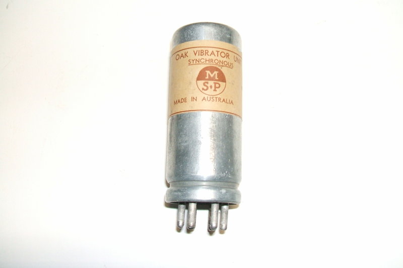
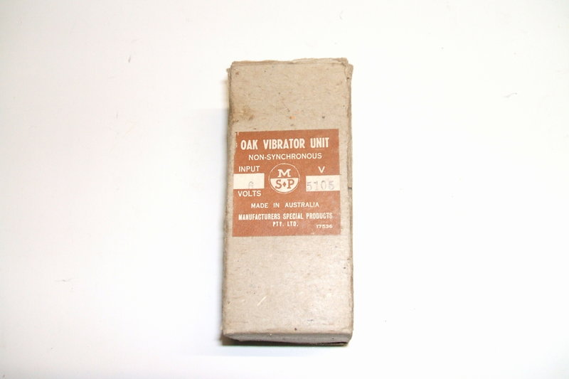
At left is the first generation of MSP labelling, and at right is
the early style box.
Good Reliability
The "series" or "separate" drive design
means the vibrator always starts, even if the main switching contacts are
worn or the supply voltage is a bit low. This is because the driver contact
is only switching the small coil current, and the contact itself is a non
tarnishing precious metal. One test showed no visible wear of this contact
after 1500 hours of operation.
With the more common shunt drive type,
the vibrator will not start if the power contacts have worn or are out
of adjustment.
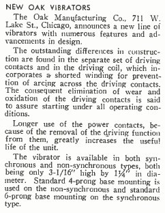
From notes in Radio Engineering, April 1935. Their prophecy of longevity
turned out to be correct.
It is because of the prevalence of the
Oak design in Australia, that reliability problems which seem so common
in the U.S. where the shunt drive type is standard, did not exist here.
To help explain this, it must also be pointed out that in the era of vibrator
powered equipment, that buffer capacitors were usually paper types with
relatively poor reliability. This has more than likely contributed to the
common "vibrators are unreliable" myth that exists. With a poorly
performing buffer circuit, the power contacts will wear quickly, and then
the vibrator will not start. In the same circumstances, the power contacts
of a series drive vibrator will also wear, but the reed will still vibrate
as normal. The effect is that the output voltage of the power supply is
still present, but gradually drops due to the descreasing duty cycle as
the contact gap increases. So, under less than ideal conditions the vibrator
is still "working". Of course, with the correct loading and operating conditions
which avoid contact wear, the shunt drive type will also have good reliability,
provided the vibrator is of reputable design and manufacture. Obviously
a non-starting vibrator is more of an inconvenience than one which simply
has reduced output, and in this regard the series drive is ultimately more
reliable.
Out of my hundred odd items of vibrator
power equipment it has never been necessary to actually replace a vibrator
(shunt or series drive); and this is over more than 35 years.
So, fear not fellow Aussies; do not take
what you read in overseas magazines and vintage radio forums as gospel,
regarding vibrator reliability. Our series drive MSP/Oak units do not have
those issues, instead lasting as long as any other electronic component.
And, if you're into restoring Astor/Air Chief car radios, it's worth looking
out for the MSP replacements for the original Ferrocart types. These are
discussed further on.
Of course, it's important to note that
unsuitable circuit design, loading, or defective buffer capacitors will
ruin even the best vibrator. With the correct component selection and attention
to power rating, an Oak vibrator is completely reliable with an extremely
long life - so long that it's really a non issue.
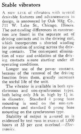
Similar release notes From "Electronics", May 1935.
Unfortunately, vibrators often fall victim
to the incessant 'tweaker' who is drawn to its moving parts like moths
to a light. Oblivious to the precision construction and careful setting
up in the factory , they twist the contacts this way and that, attempting
to repair a defective unit. The teeth marks of long nose pliers can often
be seen...
In actual fact, randomly "adjusting" a
vibrator is one of the worst things one can do. One needs an oscilloscope
to do it properly, for the timing and duty cycle cannot be accurately set
otherwise. Unfortunately, some enthusiasts cannot get past the "it's just
a buzzer" mentality.
Run into a resistive load, the vibrator primary contacts are adjusted
thus. A tweaker who jumps in with a pair of pliers and no instruments cannot
hope to duplicate this. Add secondary contacts and the mess can be imagined!
Yet, they're the first to complain about the reliability of vibrators...
Operation at Higher Voltage.
Another advantage of the separate connection
to the driving reed is that it is possible to operate the vibrator off
a higher voltage simply by connecting a resistor in series with the driving
coil. For example, a V5105 which has a 6V coil can be run off 12V with
a 22 to 27R 5W resistor in series. One model of Philips car radio, NT364V,
had this facility built in, so that the radio could be used in a 6 or 12V
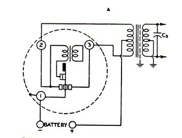
car simply by changing links under a panel. The power supply shown below
operates a 12V vibrator from a 32V supply using a 100R 3W resistor in series
with the drive coil.
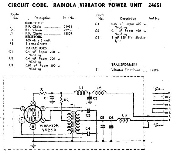
32V vibrator power supply for an AWA domestic radio. When this was
designed, 12V was the highest voltage available for the vibrator. Note
R1 to drop the coil voltage. Once 32V vibrators became available, R1 was
deleted. Incidentally, this power supply was issued with a modification
to move the buffer capacitance to the primary to eliminate contact arcing.
The Bland shaver inverter is another example; in this case a 6V vibrator is used on 12V.
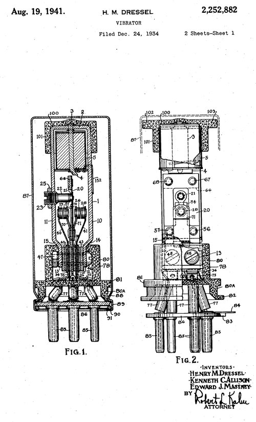
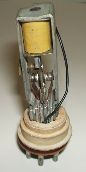
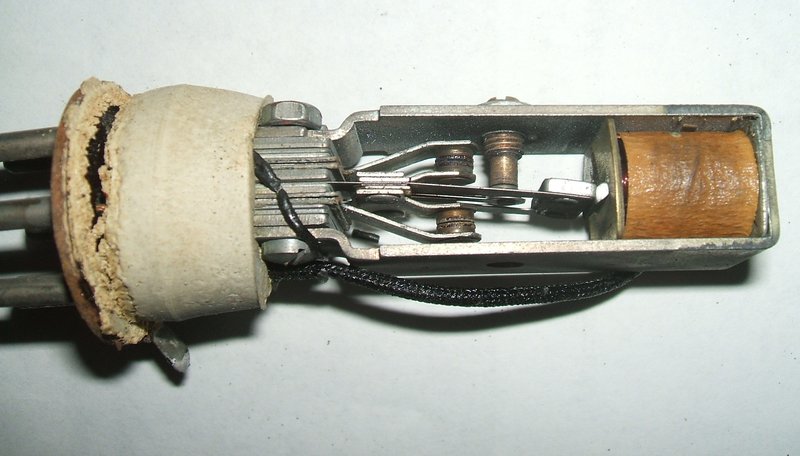
Construction of the Oak vibrator.
The design of the driving coil is unique
to Oak and was one of their patents. It will be noted on most schematic
diagrams that the Oak vibrator has a secondary winding on the driving coil
which is short circuited. This is wound with chromoxide resistance wire
and considerably lowers the Q of the driving coil. The windings are
bifilar wound. The purpose of this is to eliminate sparking at the driver
contact. It does this because the lowered Q slows down the rate at which
the magnetic flux collapses when the contact opens. The usual inductive
kick back is prevented. Other manufacturers of series drive vibrators use
more conventional spark suppression circuits with a resistor, a capacitor,
or a combination of both.
The reed is made of Swedish spring steel.
The power contacts are made of Oakalite tungsten, and the drive contact
is palladium silver alloy. The can is usually zinc, but a small proportion
were made with aluminium. The vibrator mechanism is secured to the can
by a spring clip, and is earthed to one of the pins.
Servicing.
As with most vibrators taken out of storage
after many years, the insulating film that builds up on the contacts needs
to be cleaned off. This is usually the cause of a vibrator not providing
output, whether it starts or not. The driving coil contact seldom is affected
this way, because it is made of a precious metal and does not tarnish.
It is also normally closed, and thus nothing gets in between the contacts
when not in use. Mallory mentions that the film is tungsten oxide which
forms on power contacts. However, it seems to be more prevalent in vibrators
where sponge rubber is used inside the can. In this case it appears to
be a decomposition by-product (sulphur is one possibility). The film can
be physically cleaned off the contacts by means of 600 grade sandpaper
or a fine blade such as an X-acto knife. However, care must be taken not
to upset the contact spacing. For this reason, I prefer to electrically
clean the contacts where the film build up is fairly minor. Current limited
high voltage will break through the insulation and burn it off.
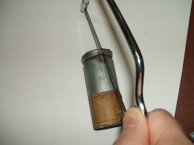
Another sensible aspect of design is that
service access for the Australian Oak vibrator is easy. Unsolder the earth
tag and remove the spring clip. The mechanism can then be slid out. In
some instances, it will be found the base of the can has expanded in diameter,
with the phenolic base a looser fit than normal. This is a result of the
constant pressure from the spring clip against the soft zinc can. The zinc
creeps over time under pressure.
Usually, it is not necessary to open the
vibrator unless it has been damaged, or after a long period the contacts
in a synchronous or dual interrupter type need to be retimed.
If the driving coil does not function
it's either: 1) the wire broken off just near the coil, 2) the adjustment
screw for the contact is a bit out, 3) dry joint in pin or at bottom of
vibrator frame. In a couple of rare instances broken or cracked reeds have
been found, and in one, the foam lining of the can had been replaced with
a type which decomposed rapidly, leaving a sticky substance between the
contacts.
To electrically clean the contacts, the following test jig can be assembled:
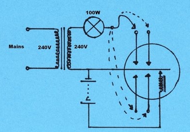
A battery of appropriate voltage is used
to get the reed vibrating. While a bench power supply can be used, there
is a risk of inadvertent damage if it should somehow come into contact
with the high voltage. High voltage is obtained from a 240V isolating transformer
and current limited to 400mA by a 100W incandescent light bulb. This is
applied to each contact in turn until the contaminants burn off. Obviously,
once this happens the bulb lights up. Because of the vibrator frequency
not being related to the mains supply, the bulb will flicker once the contacts
make. This is quite normal.
It goes without saying that no part of
the circuit, or the vibrator should be touched while the mains is connected.
The can of the Australian made Oak vibrator is usually connected to the
reed. Although the transformer provides isolation from the mains,
there is still 240V between its secondary terminals.
Note that this method of contact cleaning
will only remove oxide. It will not restore pitted or misadjusted contacts.
Disclaimer: There
are restorers who don't appreciate the dangers of a direct mains connection
and will run this circuit without a transformer. No reponsibility is taken
for undesirable results that occur.
Check all contacts
It's important to see that all contacts
are functioning, because if the vibrator works in half wave, those contacts
which are working will be damaged. Simply observing the transformer
waveform will confirm this, but the output voltage is also revealing. A
potential problem is someone who gets a vintage radio, turns it on and
find that it appears to work. If the vibrator is working in half wave,
the radio will indeed be working, deluding the owner into thinking all
is well. However, damage will soon set in, and if the contacts are badly
burned and the spring temper damaged, the long term reliability could be
poor despite efforts to repair the vibrator.
Adjustment of the Oak vibrator.
Discussion with a retired AWA employee
who worked in the vibrator division of MSP brought forth some useful information.
The vibrators were adjusted after assembly using a test panel fitted with
dwell meters and also a CRT. The vibrators were tested with a resistive
load. Apparently, this test panel was "ancient" and pre-war. The CRT was
assumed to be a 5BP1. The adjustment was done only via the side (fixed)
contacts. As it happened, the precision of manufacture was that not much
adjustment was needed anyway. A standard type of relay adjusting tool was
used; i.e. a rod with a slot cut into the end. Each primary contact was
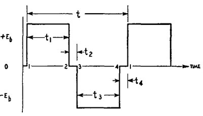
set up for 40% duty cycle with a 5% tolerance. When operating in a full
wave circuit, the duty cycle is therefore 80%.
Because the Oak vibrator operates at 100c/s,
this means each contact is set for 4ms closing time. With a calibrated
oscilloscope, the adjustment is therefore quite easy. While I could have
designed my vibrator
test panel with dwell meters, it's more accurate to use a CRO, which
these days are inexpensive and commonplace anyway. Further detail on adjustment
is given here.
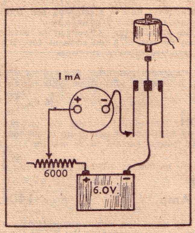
Setup for adjustment by meter.
The setup for adjustment by dwell meter
is shown above. The variable resistor is adjusted so that the 1mA meter
shows full scale deflection when the meter is connected directly to the
battery negative (or the vibrator contact held closed).. By this means,
it can be seen that when the vibrator is operating, the less than 100%
duty cycle will show up as a reading less than 1mA. The vibrator is then
put into operation, and the readings observed. Adjustment is for the primary
contacts to show 40% of full scale, and the secondary contacts to show
38%. Note that this method of adjustment has some limitations. It is suitable
only for series (separate) drive vibrators such as the Oak. The figures
given suit the Oak vibrator, which has a lesser duty cycle than some other
types. Nevertheless, the scheme could be used for other types if a known
good sample can be compared with. Obviously, the meter used must have good
accuracy to show the 2% difference between the primary and secondary contact
duty cycle. A cheap panel meter would not be suitable.
This method also relies on the contacts
being in excellent condition (it was intended for new vibrators during
manufacture). If the contacts are dirty, the time they actually make contact
may be less than the physical time they are touching. Adjusting a vibrator
with less than excellent contacts this way is likely to result in error.
This method is shown as an alternative if a vibrator must be adjusted in
the absence of a CRO, but is not ordinarily recommended.
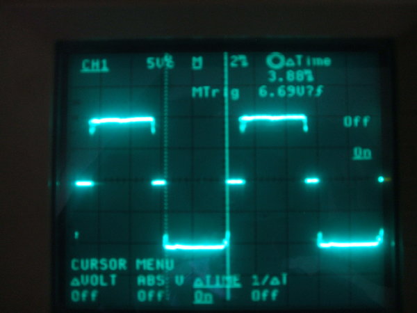
Run into a resistive load, the contacts show provide a waveform
like this. 3.88ms is within tolerance.
To obtain the correct duty cycle entails carefully bending the arms of the fixed contacts, with a narrower spacing obviously increasing the duty cycle. The vibrator primary contact adjustments have a 5% tolerance at 40% duty cycle for each contact. This means 3.8 to 4.2ms is acceptable. The above waveform was taken using the vibrator test panel which uses 8R 20W resistors for the load. The resistor values are not critical, but should provide around 500mA to 2A current flow to ensure the contacts are 'wetted'. The vibrator used for this example is from the Walbar car radio.
The same setup is used for the secondary
contacts in the case of synchronous vibrators, but instead of 4ms, the
'on' time needs to be 2% less; i.e. 3.8ms. Obviously, if the primary contacts
happen to be set at 3.9ms (such as in the above photo), then the secondary
contacts should be 3.7ms. The secondary contacts must always close after
the primary contacts, and open before.
For split reed vibrators, adjust one set
of contacts as you would with a non-synchronous type. Then, using this
first set of contacts as a reference, adjust the other set so that the
timing is identical.
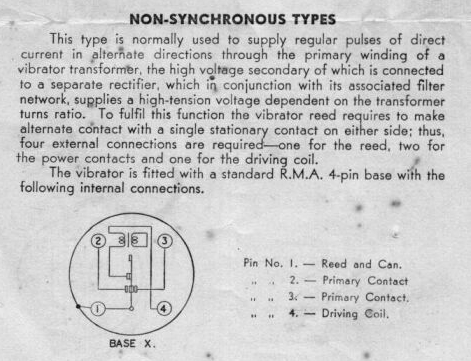
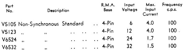
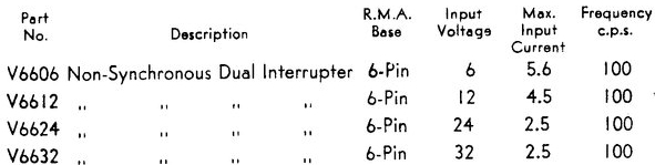
Non Synchronous types.
The basic vibrator, most commonly used
in car radios and small inverters. Where DC output is required, a valve
or other rectifier is required. Most commonly found are the V5105 and V5123
types. These were used in every AWA car radio, of the valve rectifier
type, up until the last model in 1965. Note that with all the vibrators
types listed (not just the non - synchronous types), the contact current
rating goes down as input voltage increases. This is because arcing is
more prone to occur with an increase in voltage.
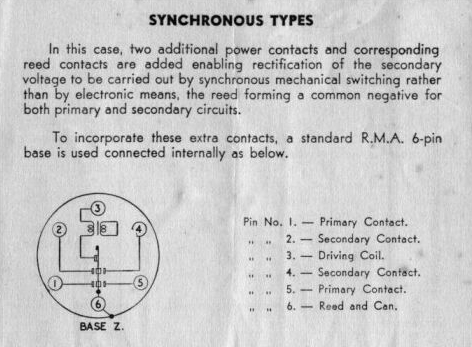
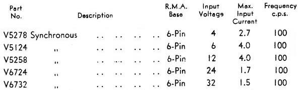
Synchronous types.
These are fitted with secondary contacts
for self rectification. Commonly used where it is undesirable to use a
valve rectifier, such as where dictated by space or power consumption constraints.
Some car radios did use synchronous types, but mostly they were used for
accumulator powered domestic radios. Note that the timing of the primary
and secondary contacts is not identical. The secondary contacts open and
close slightly later than those of the primary. The 4 volt type might cause
some curiosity. It had two popular applications. One was for portable camera
flash units where a small two cell lead acid battery was used, but more
commonly they were used for 6 volt accumulator powered radios. Here, the
vibrator is connected across the 4 volt section, and the valve heaters
across the remaining cell (2V). The idea was that by supplying the directly
heated filaments from a separate cell, it was easier to keep vibrator interference
out of the system.
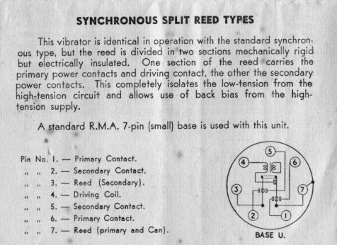
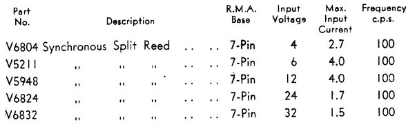
Synchronous Split Reed types.
These are mostly used in domestic accumulator
powered radios, because with directly heated battery valves an external
bias supply is often required. As the valves filaments are also the cathode,
it is not possible to use cathode bias in the same way as indirectly heated
types.
It is also possible to configure a split
reed vibrator so that it works as a full wave switch into a non centre
tapped transformer primary. The Bland shaver inverter takes this approach.
It is worth keeping this in mind where it is necessary to convert a 6V
car radio to run on 12V. By changing the vibrator to a split reed type,
it is possible to keep the original 6-0-6V transformer on 12V by not using
the centre tap.
6-12V conversion with a Split Reed
Vibrator.
Vintage cars having their 6V electrical
system converted to 12V are a fact of life, as much as the practice is
undesirable. When it comes to the radio, several options are available.
A 6 volt radio can be simply run from the new 12V supply by means of a
resistor. The resistor is selected so that with the battery 12V (i.e. not
charging), the radio receives 6V as measured on an analog meter. Why analog?
Because the current draw is not steady DC and the peculiar waveform is
more likely to give a less accurate result with a digital meter. In practice
the resistor value is somewhere around 2.5 ohms and dissipates a fair bit
of
heat; 30W is not uncommon. The exact resistor of course depends on the
particular radio and has to be selected on test.
The disadvantage of this scheme is the
wasted power and that the nominal 6V changes as the radio warms up. This
may or may not be a problem in the particular situation.
The more efficient method is to convert
the radio to 12V. For the valve heaters and dial lamp, these can be replaced
with their 12V equivalent; e.g. 12X4, 12AQ5, 12BA6, etc. If this is not
convenient, the existing valves can be rewired in a series parallel circuit.
See here for
further details.
The next thing is to deal with the vibrator
and transformer. If possible, the transformer primary could be rewound
with twice as many turns using thinner wire. Under the assumption that
the vibrator is an MSP type, a 27R 5W resistor can be connected in series
with the drive coil. Simply installing a series resistor to power either
the transformer alone, or transformer and vibrator is not recommended.
The problem is that until the valves warm up, there will be no load on
the inverter, causing excessive voltage in the transformer secondary winding
which can cause insulation failure, damage to the buffer capacitor and
arcing at the rectifier socket. Where the whole radio is fed from a resistor
this is less problematic as the valve heaters provide a constant portion
of the load.
However, there is a much more ingenious
way around the problem. It allows the original transformer to be used without
modification.
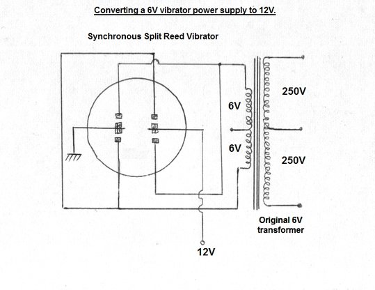
How to use a split reed vibrator to enable a 6V vibrator transformer
to operate on 12V. Note that the driving coil is not shown for simplicity.
Here, a split reed vibrator is connected
so it works as a DPDT reversing switch, applying +12V then -12V to the
full primary. In effect, the primary receives the same peak to peak voltage
that it did on 6V.
The centre tap is no longer used. The
advantage is of course the regulation and efficiency is as per original,
and the transformer needs no modification. The vibrator and its socket
do have to be replaced however, but as these items have the same appearance
as the originals, the radio will still look original. The Bland
shaver inverter uses this technique.
Of course, if the radio used a synchronous
vibrator for rectification in its original 6V form, then either a solid
state or valve rectifier will have to be fitted, but this is likely to
be preferable to replacing the transformer.
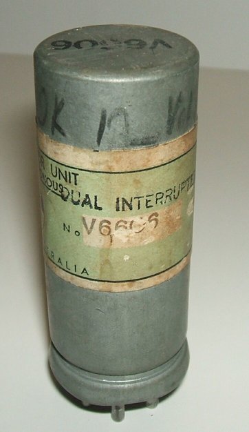
Dual Interrupter types.
These are commonly used in 240VAC inverters
or high power amplifiers, radio transceivers, etc. They are constructed
the same as synchronous types but with the contact timing adjusted so both
sets open and close at the same time. The contacts can be connected in
connected in parallel to increase current rating, or more effectively,
be used to switch two separate transformer primaries, or two separate transformers
with the secondaries in parallel. These latter two configurations
provide better current sharing between the contacts. In reality, it is
impossible to ensure both pairs of contacts open and close at exactly the
same time over the life of the vibrator, so the current rating is not actually
doubled as might be imagined. In the U.S., the term "Duplex" has been given
to this type of vibrator.
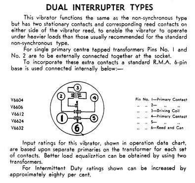
There are also types V7706 and V7712, but
data is not shown. As far has been ascertained without actually opening
one, these are the same as the V66xx types as far as connections and the
driver coils are concerned.
The dual-interrupter type became available
late 1948 / early 1949, and the first project in Radio & Hobbies to
use it was their "6-240 Amplifier", from February 1949. The article pointed
out that, previously, the highest power from a vibrator could only be obtained
from parallelling the primary and secondary contacts of a normal synchronous
type. The input power rating for this mode of operation was stated to be
30W at 6V. Of course, synchronous rectification was now not possible, requiring
a valve rectifier. With the new dual-interrupter type, the "6-240" amplifier
was able to draw a vibrator input power of 51W.
The circuit below, from Radio & Hobbies,
April 1951, illustrates the use of a dual-interrupter vibrator. It is of
a 240V AC 40W inverter, powered from either 6 or 12V. The transformer is
a Ferguson VT146 which is designed for 6 or 12V operation by means of a
tapped primary.
For 6V, the two primary windings are fed
independently from each set of vibrator contacts. This provides more even
current sharing. The 12V configuration simply has the two sets of contacts
in parallel, but as the current is halved at this voltage, the current
sharing is less critical.
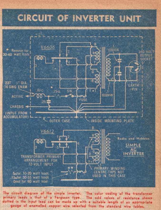
This circuit from Radio & Hobbies, April 1951, illustrates how
a dual-interrupter vibrator is used. Contacts may be paralleled, or drive
separate primary windings.
Ferris car radios and inverters.
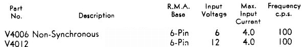
A type that seems to be unique to Ferris
is the six pin based V4012 and V4006. These are simply the same as their
4 pin counterparts except for the base. Internally, the V4012 is the same
as the V5123 and the V4006 is the same as the V5105. Why Ferris chose to
use a 6 pin base is a mystery. Perhaps it's because the extra pins exert
a firmer grip on the vibrator in the socket.
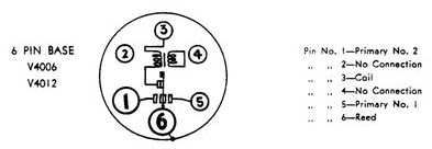
With the standardisation of pin connections, these types actually have the same pin connections as the synchronous and dual interrupter types, except there's no extra set of contacts. This means that one often finds dual interrupter or synchronous vibrators plugged in instead, even though the extra contacts are not being used. It's a worthwhile modification to simply link the other socket pins to bring the extra contacts into being in parallel. While this has limited merit with synchronous types due to the later closure of the secondary contacts, it means that although current rating won't be greatly increased, the secondary contact will take over if something goes wrong with the primary contact. No doubt radio servicemen found it convenient that any MSP six pin vibrator could be plugged into these sets, without having to do any socket rewiring.
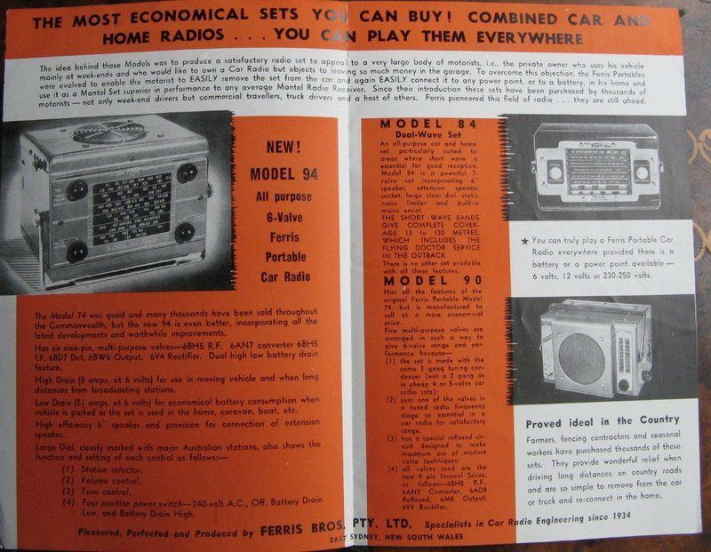
The reliability of Ferris car radios was partly due to their use
of the MSP Oak vibrator.
Astor car radios.
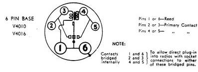
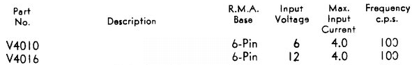
Type V4010 and V4016 are interesting
types. They also have a 6 pin base and are non synchronous. They are designed
as a replacement for the shunt driven Ferrocart
vibrators used in Astor car radios. Four pin Ferrocart vibrators actually
use a four pin Delco base. This is effectively a UX-6 base, with pins 2
and 5 physically omitted.
V4010 is 6 volt and replaces the Ferrocart
PM237, and V4016 replaces the 12 volt PM238. These vibrators are immediately
obvious because adjacent pairs of pins are strapped together on the underside.
The straps are so connected that the three active pins of the V4010/V4016
match up with those of the Ferrocart type. However, some versions have
the strapping internally.
Otherwise, they use the same components
as the normal series drive non-synchronous types, except that the drive
coil takes its feed from one of the power contacts. Also, the drive coil
is of higher resistance, since the applied voltage is twice the supply
voltage, due to the transformer action.
Unlike the shunt drive Ferrocarts which
the V4010 and V4016 replace, the Oak design retains their separate drive
contact, despite the use of shunt drive circuit. This means a considerably
greater life expectancy can be obtained before any adjustments are required.
Separate drive contacts used with the shunt drive circuit.
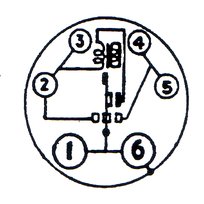
Depending on the source of data, the internal schematic shows the
V4010/V4016 as either a true shunt drive type, with no separate drive contact,
or as has been confirmed with all the examples in my collection, a separate
drive contact is used.
Types V4011 and V4017 are electrically the same, but without the strapped pairs of pins. It is not clear why the two variations exist, since they would appear to be completely equivalent, when plugged into a set designed for four pin Ferrocart vibrators. Indeed, I have never seen the V4011 or V4017. The likely answer appears that some of the "four pin" Ferrocart sockets were just that, and did not have holes for pins 2 and 5. Therefore a UX-6 base vibrator cannot be plugged in, short of removing pins 2 and 5. It appears V4011/V4017 are made without pins 2 and 5.
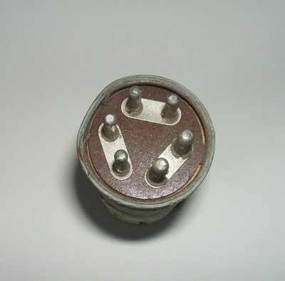
The three strapped pairs of pins immediately identifies the vibrator
as a V4010 or V4016. Note that some examples have the pins strapped internally.
Although I have not done tests, it would appear necessary to check the buffer capacitor value when using an MSP to replace a Ferrocart in view of the PM237 and PM238 operating at 150c/s. On the lower frequency of 100c/s produced by the MSP, the buffer capacitor may need to be increased.
Aged types.
Prefixed by "A", these are painted black
to enhance cool running. A typical type is AV5948. They are run for an
ageing period prior to final adjustment. Mostly, they appear in mobile
two way radio applications, such as the AWA Carphone.
Reverse polarity types.
Suffixed by "R"; for example AV5948R.
These are synchronous types that have the secondary contact connections
swapped over, so that the output polarity is reversed from normal. An application
for this is where a radio might be transferred to a positive earth car
from one which was negative earth, or vice versa. Instead of swapping over
the transformer connections, a quicker alternative is to simply change
the vibrator to the other type. They are also used where split reed synchronous
power supplies are used in series. This is because the secondary centre
tap of one transformer has to be positive (the normal situation), while
that of the other has to be negative in order for the voltages to add.
On this note, the AV5948 is used with
the AV5948R in one of the AWA Carphone power supplies to provide 150V on
receive and 300V on transmit.
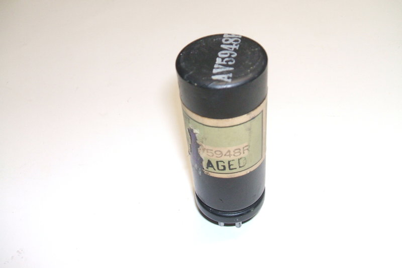
An "Aged" reverse polarity type, AV5948R. This is a 12V split-reed
synchronous type.
AC types.
The final, rather obscure type, is one
in which AC is applied to the driving coil. The vibrator functions as a
switch, synchronised to the mains. So far, the only application I have
seen such a type in is a mains operated ignition coil tester.
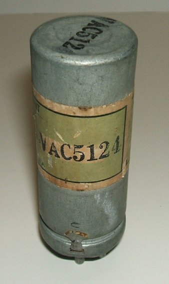
Type VAC5124 has a 6V AC driving coil.
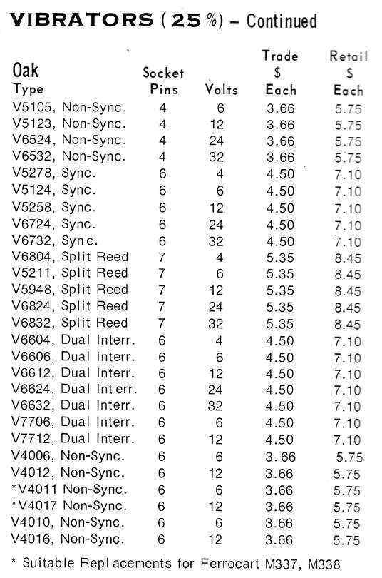
Radio Parts Catalog 1968-1969.
Oak Vibrators in England.
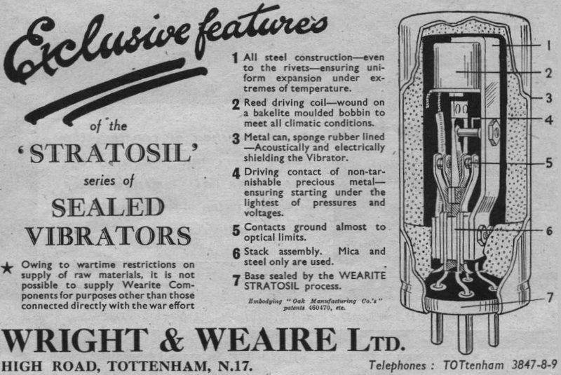
The English company, Wright & Weaire was another establishment outside the U.S. making Oak vibrators, under their "Wearite" brand. However, unlike the Australian MSP version, the Wright & Weaire version does not externally look like the original Oak, and the numbering system is totally different. Instead of V5123, for example, W&W will use NS/12. The can is of a wider diameter, and the base is crimped in place. The can is aluminium instead of zinc. Looking at the cut away diagram above, we can see that the can contains much more rubber for acoustic insulation. The entire can is lined, whereas the original design is not insulated against noise except for at the top and bottom. Presumably the thicker zinc stops most of the noise transmission by itself, whereas thin aluminium is not so effective. It is unfortunate that the crimped can construction has been used, but internally these vibrators should be as good as any Oak design.
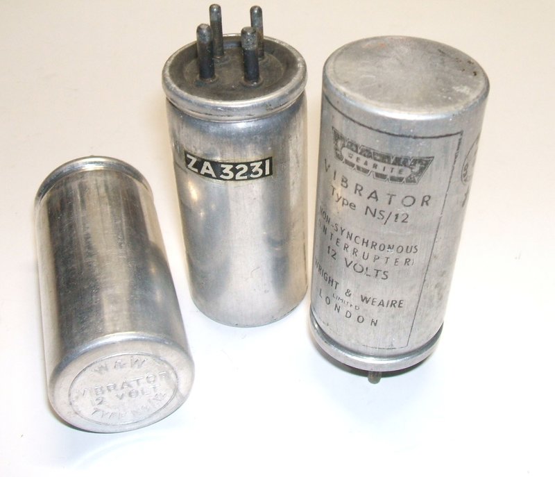
Wright & Weaire vibrators type NS/12.
Oak Vibrators in the U.S.
Unlike the Australian version,Oak in the
U.S. changed the design of the can. The original zinc can with spring clip
gave way to wider diameter zinc and aluminium cans. One type of aluminium
can has a ribbed surface, presumably to aid heat dissipation. These latter
types are all of the crimped construction. Oak vibrators were also rebadged
under other names including Raytheon, General Electric, and Terado.
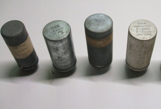
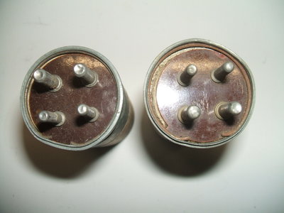
Examples of U.S. made Oak vibrators. At the far left is the
type on which the Australian AWA/MSP version is based. The finned can type
at right was also rebadged by Terado, and it seems, Raytheon and GE.
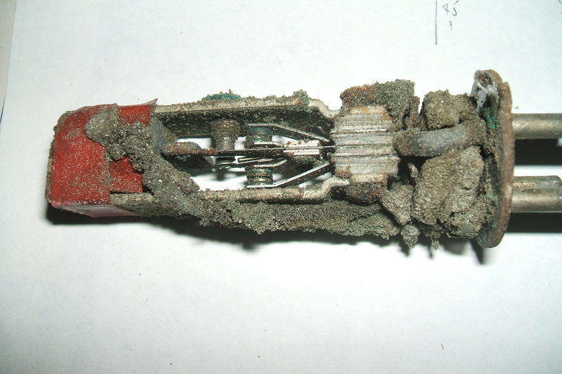
It says " OK 12 Volt". Some clown had decided to use a 6V vibrator on 12V because it appeared to work. I dreaded what I'd find inside, and indeed the mechanism and sponge rubber was coated in a black substance.
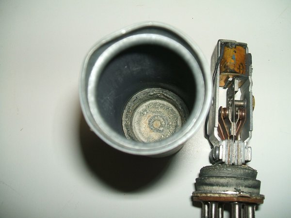
Don't run a vibrator with incorrect coil voltage, although it might
"seem OK".
Prior to taking the photo I had cleaned
it up, but the black deposit is still evident around the sponge rubber.
This kind of component abuse is always
appalling, in this case almost ruining a perfectly good vibrator. Thankfully,
the driving coil appears to have survived, although something seems to
have exuded from it particularly at the top of the bobbin. It would
appear that someone needed a 12V type but didn't have one, and discovered
that a 6V type would work instead. Yes it will, but with excess driving
coil current and the resultant overheating, the arcing at the driving coil
contact, and of course the excess reed swing giving an extra hammering
to the contacts. Who knows how long it would have taken to burn out the
driving coil. If only a 27R resistor had been connected in series with
it. It's rather reminiscent of people with vintage cars that feed 12V into
6V starter motors.
And yet, you can be sure whoever did this
would be the first to complain about vibrators being unreliable or some
such nonsense.
This V4016 shown below, refused to start. Upon opening it, the reed could be seen to be catching on the solenoid pole piece. The reed also was not centered at rest. In an attempt to correct this, it was found the reed was broken.
Reed catching on pole piece. It was found to be cracked.
This broken reed came from a fellow HRSA member. It was from a V4012. It should be pointed out these are the only two broken reeds I have seen in Oak vibrators.
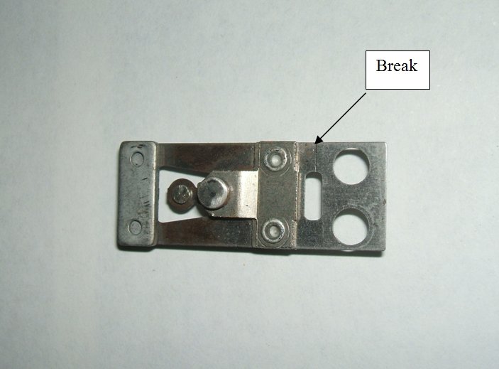
Reed breakage is one fault that cannot be repaired, but fortunately
is a rare occurrence.
Another vibrator that wouldn't start - a V5105. Someone in the past had replaced the foam rubber. Unfortunately, they had used a type of foam that disintegrates into a sticky corrosive mess. After a good clean up, this vibrator worked perfectly. The connecting wires to the base had also been replaced with ordinary rubber insulated type. This had gone brittle. The best kind of wire for this is ultra flexible instrument lead wire.
Don't use this kind of foam to replace the acoustic insulation!
Zinc can creeps under pressure from spring clip.
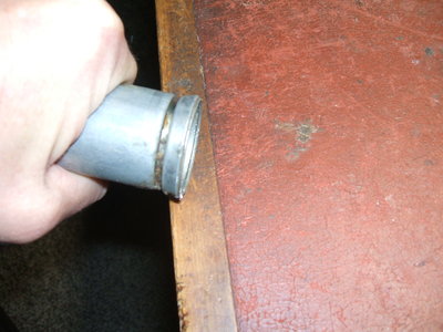
Slot is cut to allow zinc to return to original shape. Can edge
is rolled on hard surface to bring the shape back to original.
Base Repair.
The foam rubber which supports the mechanism
on the base can either be in perfect condition, or it can have totally
disinitegrated. Sometimes the rubber has hardened to the point of crumbling
apart and can be heard rattling around inside the can. There is also a
rubber cap in the top of the can, in which the top of the mechanism rests.
The foam rubber can be replaced with modern "Aerotape".
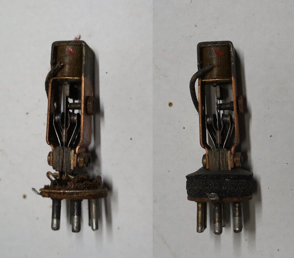
Base foam deteriorated on left, and rebuilt with Aerotape on the
the right.
Three discs of Aerotape are cut to the
diameter of the base. Two are stuck down to the base, and then the mechanism
is attached by resoldering the wires. Use a jeweller's screwdriver to poke
holes in the foam for the wires.
The third disc has a U shaped slot cut
in the centre so it goes around the bottom of the mechanism.
Usually, the rubber cap at the top of
the mechanism lasts better than the base, but if it needs replacing, the
same Aerotape can be used there too. However, the thickness is such that
if used for the top portion of the cap, the mechanism will have pressure
against it and will not be able to "float" freely. This is undesirable
because it alters the vibrator operation. Instead, a thin piece of felt
does the job, and Aerotape is used just for the side piece. Ensure that
when reassembling, that the mechanism can indeed float freely.
(The vibrator shown in the above photo
is from this
Breville radio).
| Volts | Coil Resistance | Inductance | Q | Examples of types |
| 4 | 8.5R | 640uH | 0.162 | V6804 |
| 6 | 12R | 1.1mH | 0.17 | V5105, V5124, V6606, V7706, V5211, V4006 |
| 12 | 35R | 1.1mH | 0.09 | V5123, V5258, V6612, V7712, V5958, V4012 |
| 6 (shunt circuit) | 24R | 1.2mH | 0.11 | V4010 |
| 12 (shunt circuit) | 73R | 1.5mH | 0.06 | V4016 |
| 24 | 131R | 4.06mH | .08 | V6724, V6824, V6624, V6524 |
| 32 | 230R | 3.64mH | .054 | V6632, V6532, V6732, V6832 |
The number of pins further narrows down the types. For example, 4 pins means a non-synchronous type such as V5105 or V5123. Six pins means synchronous, dual interruptor, or Ferris type non-synchronous. The Ferris types V4006 and V4012 can be identified in that pins 2 and 4 show no connection whether the vibrator is operating or not. Six pins could also mean it's a Ferrocart replacement V4010 or V4016, and checking for continuity between adjacent pairs of pins will confirm this.
To differentiate between synchronous and
dual interruptor types, the timing of each set of contacts has be examined
on a CRO by using a set up like this.
Seven pin types are split reed synchronous,
and once the voltage rating has been determined, the type can be further
narrowed down. However, this does not determine if it is an "R" (reversed)
suffix device. To do this requires the primary and secondary contact timing
to be examined on a CRO, or simply by using the vibrator in a known device
and seeing if the output voltage is reversed. Note that reversed types
are in the minority and not generally encountered with domestic radio equipment.
Ferrocart replacement types V4010 and V4016, are immediately identifiable by their three pairs of strapped pins.
Of course, if one wishes to open the vibrator for examination, it can be narrowed down to a few types. However, it is a shame to break the stamped soldered seal on a prisitine N.O.S. type just to do this.
Old Type Numbers.
Initially, Oak vibrators were supplied
using a different numbering system with two digits and two letters. This
was later dropped, and the Vxxxx system was used exclusively.
| Old Type | Later Type |
| 17XH | V5105 |
| 18XH | V5123 |
| 185XH | V6524 |
| 33ZH | V5278 |
| 35ZH | V5124 |
| 36ZH | V5258 |
| 365ZH | V6724 |
| 63UH | V6804 |
| 35UH | V5211 |
| 66UH | V5948 |
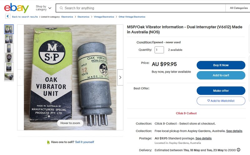
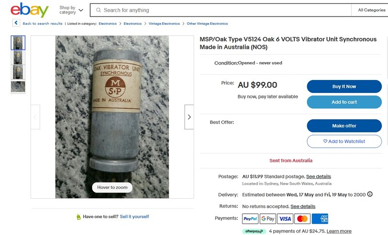
A hundred bucks for a vibrator?
This interesting eBay ad prompted the question
of what is a vibrator worth. Well, certainly not $100! The seller obviously
visited this site, because the ad title is partly cut and pasted from this
page's heading.
About a week later up came another ad:
Another seller jumps on the $99 vibrator bandwagon.
Obviously, the second seller saw the first
ad and decided that's what vibrators are worth. Clearly, both sellers are
not familiar with radio vibrators.
Generally for typical radio vibrators,
I don't pay more than about $5 each. In the past I would sometimes pay
$10 for a new in box Oak, but have enough now not to need to pay that much.
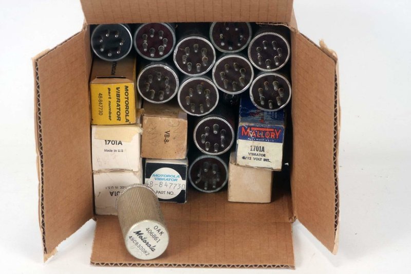
When I occasionally buy a bulk lot of
vibrators from the U.S., they work out to no more than about $5 each. As
an example, I recently bought a lot of nine vibrators from the U.S. for
US$5.00. That works out to about one Aussie dollar per vibrator!
This
lot of 19 vibrators cost only $14.00. True, the postage puts the cost
up, but still usually works out favourably when buying a bulk lot.
